01
The engineering challenge
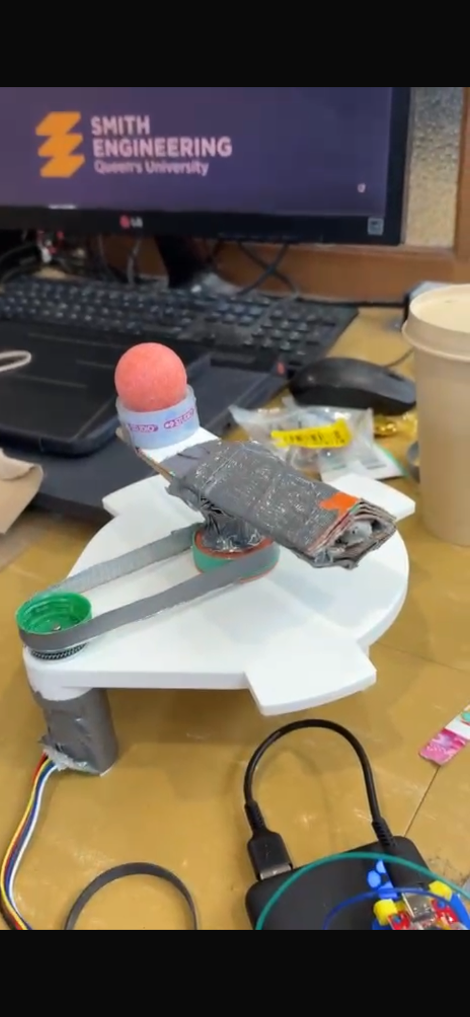
For a simulated prosthetic-manufacturing workflow, our team built a motor-driven indexing mechanism to move a simulated femoral head between picking, laser-etching, and surface-mapping stations. The challenge was to reduce motion time while holding the payload securely and stopping at the required angles.
This was an educational prototype and demonstration, not a production medical device. The project included mechanical design, reclaimed-material fabrication, analysis, motor testing, and control-system integration.
02
My contributions within the team
I worked with the team across concept development, mechanical design, fabrication, calculations, testing, and controls. We completed the tasks collaboratively; the prototype and results shown here are shared team accomplishments.
The motor-control foundation was course-provided code by Jason Harris; our work focused on integrating it with the mechanism and evaluating system performance.
03
Motion sequence & constraints
| Step | Movement | Required dwell |
|---|---|---|
| Picking → laser etching | 108° clockwise | 13.5 s |
| Laser etching → surface mapping | 198° counterclockwise | 9 s |
| Surface mapping → picking | 90° clockwise | End of cycle |
The payload follows a 60 mm radius path. The two required dwells total 22.5 seconds, so improvements in overall cycle time have to come from motion and settling.
- Support only the lower 10 mm of the simulated femoral head; do not adhere it to the holder.
- Mount to the supplied station and keep its markings and angle indicators visible. The brief flags assemblies exceeding 160 mm diameter as a potential obstruction.
- Use the supplied Pico H, FIT0521 gearmotor, TB6612FNG driver, battery pack, and power board.
- For rotational transfer, the driver and driven speed ratio must differ by at least 25%.
- Use available materials without purchased devices or specialized fabrication such as machining, laser cutting, or 3D printing.
04
Choosing the mechanism
We compared three belt-driven concepts: a suction-supported arm, an arm with mechanical spindle support and a counterweight, and a lower platform with a circular seat. The mechanical-support arm was selected using a weighted evaluation of positioning, constraints, retention, reliability, manufacturability, belt integration, and cycle time.
| Concept | Score / 100 | Key consideration |
|---|---|---|
| Suction-supported arm | 66 | Dependence on suction retention |
| Mechanical-support arm — selected | 78 | Best combined fit with constraints and available materials |
| Platform with circular seat | 74 | Lower retention score in the team evaluation |
The matrix supported a feasible construction choice; it was not a measured performance comparison of completed prototypes.
05
Mechanical design & fabrication
The prototype transferred motion from a small bottle-cap driver pulley to a larger driven pulley through a duct-tape belt. A support arm carried the simulated femoral head. Cardboard formed the structure, while washers, nuts, and the supplied gear helped locate the pulleys and reduce shaft movement.
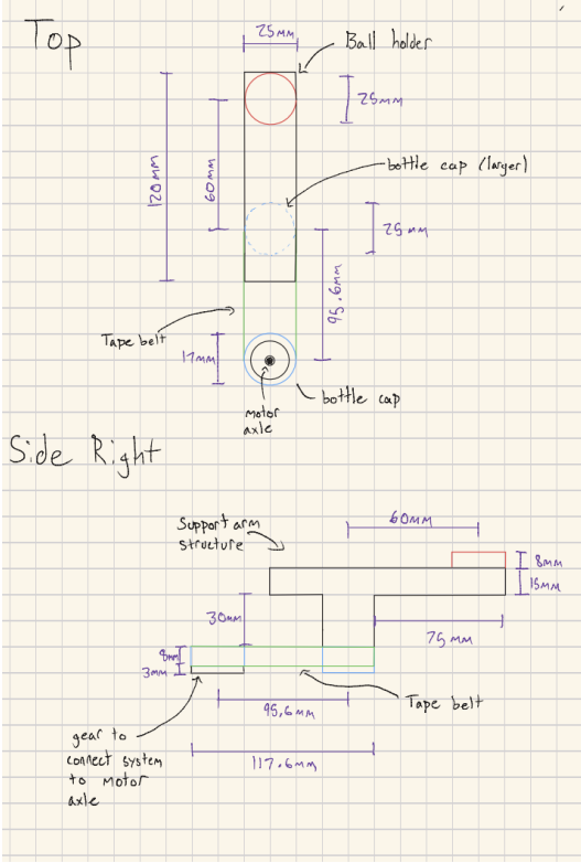
Duct tape and fast-drying epoxy secured the arm to the driven assembly. These assembly adhesives were separate from payload retention: the head itself was seated mechanically. The report describes a 25 mm circular seat and a 120 mm arm, with the head positioned 60 mm from the rotation axis.
06
Iteration: traction versus drag
| Observed issue | Change | Tradeoff or remaining limit |
|---|---|---|
| Motor could not overcome initial belt drag | Reduce the exposed duct-tape adhesive using fabric | Less sticking, but residual drag remained |
| Belt slip and inconsistent motion | Adjust belt tension and add an elastic around the driven pulley | More traction could also increase resistance |
| Pulley vibration and shaft movement | Use washers, nuts, and the supplied friction-fit gear as locating elements | Reclaimed caps still limited concentricity and dimensional precision |
The central mechanical tradeoff was not simply maximum friction. The belt needed enough traction at the pulleys to transmit torque, while avoiding adhesive drag and contact with the chassis. Changes in belt adhesion and tension also changed the behaviour seen by the controller.
07
Kinematics & force analysis
The report gives pulley diameters of 30 mm and 43 mm. Their diameter ratio is 43/30 ≈ 1.433. Under a no-slip assumption, the driven pulley turns at about 69.8% of the input speed: a 30.2% reduction relative to the driver.
The report uses 77.5 rpm at 80% duty under an assumed 100 g motor-test load. The resulting 54.1 rpm output speed and 0.1217 m/s belt speed are analytical estimates, not measured arm performance. The report notes slower motion in practice because of friction and belt behaviour.
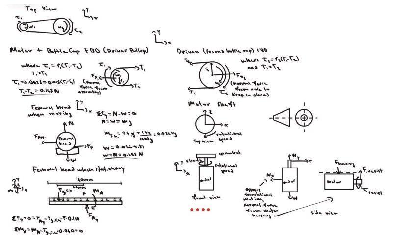
The team considered payload weight, support reactions, belt forces, and shaft loading. The report uses a 26 g payload, giving a weight of approximately 0.255 N. Vertical force balance alone does not establish retention during acceleration or braking; the observed retention during prototype trials is reported separately below.
08
Motor control
The team used encoder-based position control on a Raspberry Pi Pico H. Tuning balanced the response needed to overcome friction against overshoot and settling at each station. The implementation built on course-provided motor-control code by Jason Harris.
09
Testing & documented outcomes
| Measure | Documented result | Evidence limit |
|---|---|---|
| Cycle time | Below 27 s, as stated in the report conclusion | No individual cycle timings or comparative baseline supplied |
| Dwell timing | Report states the ±0.5 s rubric band was achieved | No raw timing measurements supplied |
| Station positioning | Performance section reports approximately ±4.5°; analysis slide states 4–6° error | Conclusion sections also claim about 2° or less; the records conflict |
| Payload retention | Report states no shift or ejection during testing | Demonstration observation, not a validated operating envelope |
The accuracy statements are inconsistent, so this case study does not claim ±2° performance or perfect indexing. The evidence supports a working course prototype with reported timing and retention success, alongside unresolved positioning error.
10
Lessons & next steps
This project connected mechanical construction quality directly to control performance. A controller can adjust motor motion, but a compliant or slipping transmission makes arm position less predictable. Improving the belt and pulley interfaces is therefore part of improving the control system.
- Evaluate a more elastic belt, as proposed in the report, while measuring slip and drag rather than assuming that more friction is always better.
- Improve pulley alignment and support stiffness within the course fabrication constraints.
- Record station error and cycle timing for repeated trials using one consistent measurement method.
- Retain the final PID sketch and tuning values alongside those measurements to make the results reproducible.
These are proposed improvements, not completed upgrades.