01
From CAD to an experimental platform
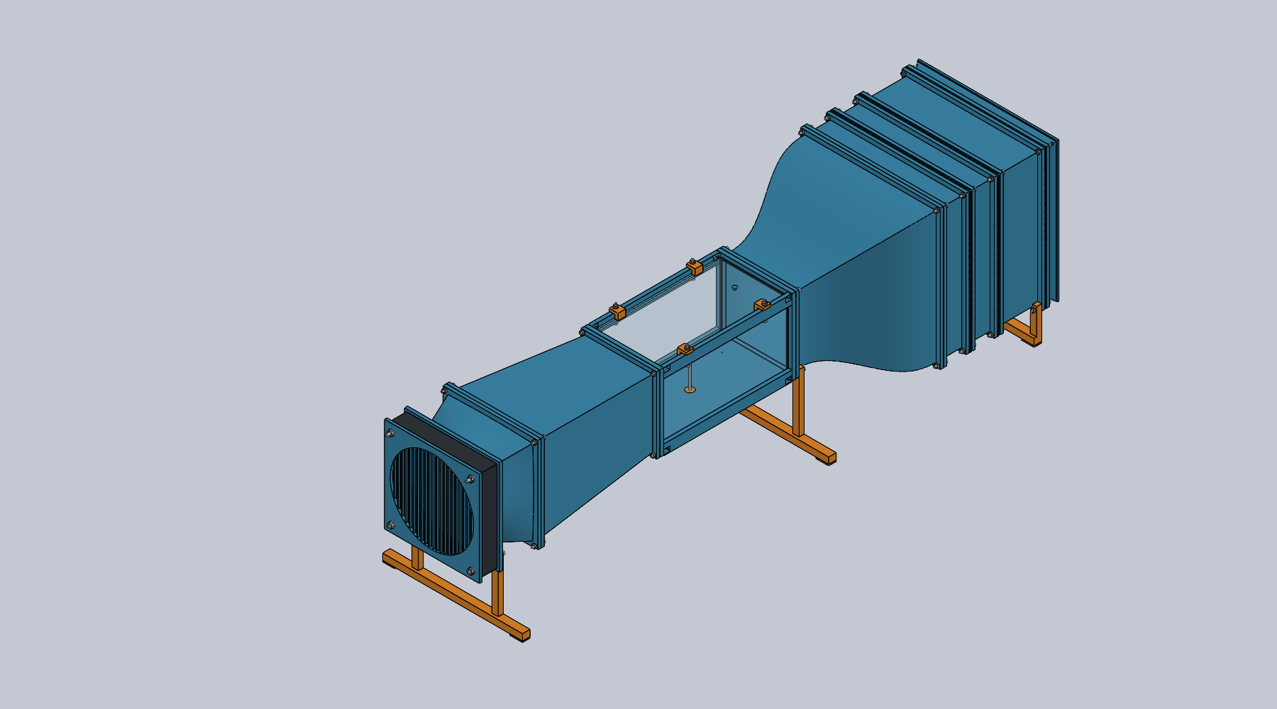
This project is a desktop wind tunnel intended for future airflow experiments. The design uses an open-circuit suction layout: a downstream fan draws air through a conditioning chamber, contraction, clear test section, and diffuser.
The CAD is complete. Testing remains future work, so there are no measured airspeed, flow-uniformity, turbulence, or aerodynamic-force results to present yet. The current milestone is a documented mechanical design with native SolidWorks parts, an assembly, and printable part exports.
02
Initial planning & design iterations
I developed the initial requirements, calculations, and concept sketches, then iterated the design before using AI assistance to generate the SolidWorks model from my detailed requirements. The CAD phase is complete; physical testing and airflow validation remain future work.
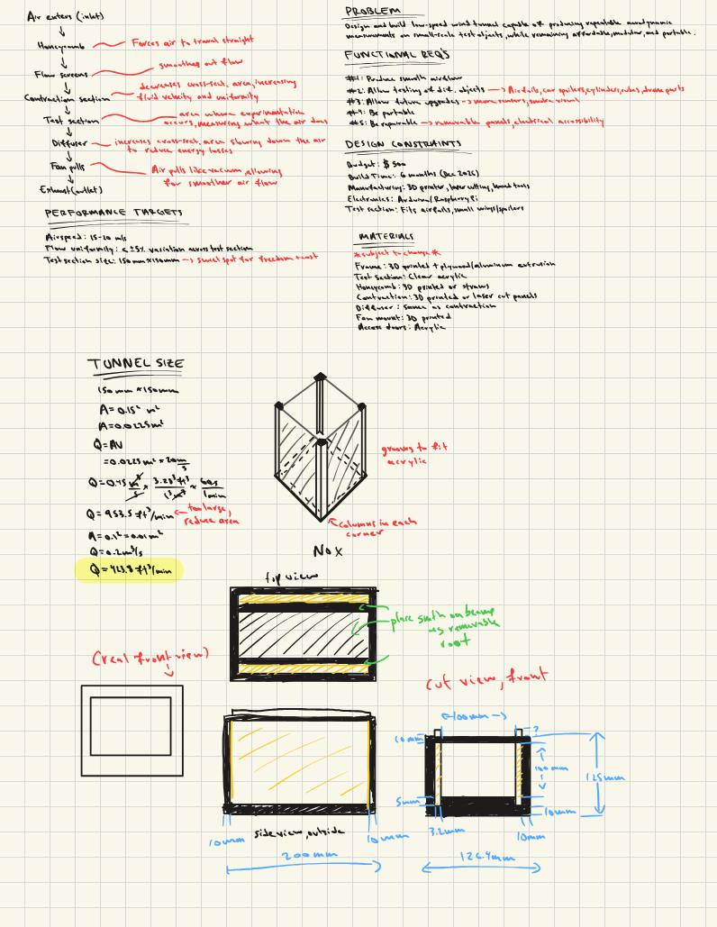
The early notes explore a 150 × 150 mm test section and airspeed targets of 15–20 m/s. The final CAD uses a 100 × 100 mm test section, and its design basis proposes investigating 2–4 m/s during commissioning. These represent different stages of the project, not measured improvements.
For the same volumetric flow, a smaller test section gives a higher mean velocity but less room for a model. The area change from 150 × 150 mm to 100 × 100 mm reduces the required volumetric flow at any given velocity to about 44% of the earlier value. Actual performance still depends on the fan operating point and tunnel losses.
03
Design envelope & flow path
| Element | Design geometry | Purpose |
|---|---|---|
| Conditioning chamber | 200 × 200 mm clear section | Houses a removable straightener and two screens |
| Contraction | 200 × 200 to 100 × 100 mm; 180 mm long | 4:1 reduction in cross-sectional area |
| Test section | 100 × 100 × 200 mm | Clear viewing area and access to the model |
| Diffuser | 100 × 100 to 130 × 130 mm; 200 mm long | Gradual downstream area expansion |
| Fan transition | 130 mm square to 130 mm round | Connects the diffuser to the downstream fan |
| Overall envelope | 868 mm nominal length; 218 mm maximum width | Sized as a long desktop instrument |
The layout prioritizes a usable test section and gradual duct transitions over minimum overall length. The 200 mm diffuser gives a nominal wall half-angle of 4.29°; shortening it would increase that angle.
04
Flow conditioning & contraction
The inlet chamber accommodates a removable square-cell straightener followed by two commercial woven screens. The straightener has nominal 6.4 mm clear cells, 0.8 mm walls, and a 48 mm length. Its length-to-clear-cell ratio is 7.5. Explicitly modeled channels allow the geometry to be checked in the slicer.
The contraction uses a sampled fifth-order wall profile between the 200 mm chamber and 100 mm test section. The design basis specifies zero slope and curvature at both ends; the CAD loft still requires inspection for local smoothness.
These geometry choices establish a design basis for conditioning the flow. Their effectiveness will be assessed by measurement after construction; CAD geometry alone does not establish flow quality.
05
Access, visibility & instrumentation
Two clear side panels and a removable acrylic lid provide visibility into the test section. Four clips release the lid vertically, allowing model changes without removing the main contraction or diffuser.
- A replaceable floor interface accepts a model-support bushing or a flush blank plug for empty-section tests.
- A 3 mm model stem has external height and angle adjustment below the floor.
- Pressure-tap provisions sit near the test-section inlet and outlet, with tubing connections outside the flow.
- A plugged lid port provides access for a future smoke probe.
- The floor interface leaves room for a future force-balance adapter; no force balance is included in the current design.
Keeping clamps and fasteners outside the main flow opening reduces avoidable obstructions. Any model, support stem, or inserted probe will still need to be included in the blockage assessment.
06
Design for fabrication & assembly
The construction plan combines printed duct modules and supports with cut acrylic, commercial mesh, a fan, seals, and standard fasteners. The modules use bolted flanges so the straightener, screens, test section, and fan remain accessible for maintenance.
| Feature | Documented provision | Check before building |
|---|---|---|
| Print envelope | 23 printable STL designs; largest footprint 218 × 218 mm | Confirm actual usable printer area and support/brim requirements |
| Duct walls | Nominal 2.4 mm walls; 0.8 mm straightener walls | Inspect extrusion paths and clear channels |
| Acrylic fit | 199.6 mm panel length in 200 mm frame spacing | Measure sheet thickness and print a tolerance coupon |
| Seals | Recessed external sealing interfaces | Check compression, leaks, and intrusion into the bore |
| Cassette hardware | Recessed screws fitted before adjacent ducts | Confirm tool access and screw engagement during dry assembly |
The native assembly uses fixed placements with a script-controlled axial layout. Contraction length, diffuser length, and model-stem height have supported controls; it is not a fully mated assembly with every interface driven by a single master parameter.
07
Resolving mechanical interfaces
The verification notes record corrections to hardware collisions and access: recessed cassette screw heads, smaller outside-diameter M3 washers, relocated upper frame bolts, raised floor attachment screws, and inlet relief for hex-key access.
Panel clearances were also introduced: the 199.6 mm side panels and lid leave 0.2 mm at each end of the 200 mm frame spacing. These are nominal CAD clearances, and their suitability still depends on real acrylic thickness and printed tolerances.
The design balances modularity with assembly order. The complete test cassette is assembled on the bench before adjacent ducts are attached; routine model access then uses only the removable lid.
08
Completed CAD checks
| Check | Recorded result | Scope |
|---|---|---|
| Native parts | 45 part files checked, each with one solid body and no reported feature errors | Saved nominal configuration |
| Print envelopes | 23 STL designs fit a 220 × 220 × 250 mm envelope in suitable orientations | Does not include a successful physical print |
| STL mesh checks | No open or non-manifold edges reported | Triangle-edge audit at the documented matching tolerance |
| Interference review | 12 reported pairs classified: 10 screw/pilot-bore overlaps and 2 tiny numerical contacts | Nominal geometry; not a tolerance-stack analysis |
| Service access | Lid, screen, straightener, and fan access reviewed geometrically | No physical assembly trial or swept tool-volume simulation |
These results come from the saved verification records accompanying the AI-assisted CAD package; they are not presented as checks I independently performed. They document the scope of the nominal design review and remain separate from physical fit, fan vibration, leakage, and airflow validation.
09
Performance targets to investigate
The design basis proposes 2–4 m/s as an initial commissioning range to investigate. This is a target range, not a demonstrated operating capability. Fan operating point, pressure losses, leakage, and model blockage will determine the actual speed.
For initial quantitative experiments, the design basis aims to keep combined model-and-support frontal area below approximately 500 mm², or 5% of the 10,000 mm² test-section area. This is a design guideline; model suitability and any needed blockage correction will be reviewed for each experiment.
10
Next steps: build, commission, test
- Print interface coupons and verify panel fit, holes, clips, and seal compression.
- Fabricate and dry-assemble the modules; inspect screw access, panel insertion, internal alignment, and guard clearance.
- Check support stability, cable routing, leakage, and fan vibration.
- Map empty-section velocity on at least a 5 × 5 grid at several fan settings, away from the immediate wall region.
- Compare blank-plug and model-stem baselines, then record pressure drop and repeatability.
- Select test models and measurement methods, and document experimental results alongside the CAD.
These activities are planned. The case study will be extended with build photographs, test methods, data, and design changes as that work is completed.